Builds : Waterdrop Rig Part 1
What do I want and how do I actually do it…
Those were the two big questions I faced entering in to this project. Now anyone that knows me personally will be aware of the fact that as well as being a massive nerd, I am, at my very core, an engineer. It is way more than a job for me and I spend most my time asking myself “could I make that” or “could I make that better”.
Now, about four years ago I had my first and only experience with waterdrop photography. Being honest, it was great fun, I got some, for my experience at the time, great photos out of it but the time consuming, elaborate macgyver style rig I had produced did not encourage me to ever try it out again. It was one of those setups and experiences where you spend so long just trying to get the whole system to work together that you never really get a chance to hone in on a really good shot as there’s so little control over what’s happening (a pin pricked bag of water above a mug will do that to you).
I’ve since got much (much) better at photography, my equipment has got better, and now that I’m no longer a student I feel like a have a bit more free time in the evenings to experiment with a few things so I have decided to revisit an old idea of building a waterdrop control rig that will accurately handle all the timings and droplets for me so I can really focus on getting the photo at its best.
This part 1 is intended to be a little introduction to what I’m hoping to achieve, how I will achieve it and what I’ve done so far and will be addressing that first question I opened with, “what exactly do I want”.
This was definitely one of those questions best answered with a bottle of wine and some relaxing music in the background and armed with those tools I came up with what I, for now, think is a pretty complete feature list for the controller that should let me do some really interesting things.
- Camera shutter and focus control.
- Support for firing two flashguns.
- Ability to use an optional infrared gate to trigger the timing sequence.
- Support for three independent solenoid valves that produce the droplets.
- Each of these valves should allow up to three drops per sequence to be produced.
- Each of the delays between individual drops and individual valves should be configurable.
- The droplet sizes should be independently configurable (by adjusting the time the valve is on).
- Ability to “flush” the system when finished.
- Ability to set a main trigger delay time. i.e the time in which the flashes trigger from the first drop.
- Support for multiple exposures: flash firing multiple times. Again this frequency/delay should be configurable.
In my opinion it’s a fairly comprehensive list and I’m a little worried about implementing all this support in one go, should be an good challenge for my programming skills.
Constructing the frame…
Unfortunately I don’t have any pictures of the design process but it’s fairly straightforward. I wanted something sturdy, relatively professional looking, and not going to be a complete pain to construct. I opted to use t-slot extruded aluminium, for those who have not used this before it’s fantastic for quickly throwing together framework and was perfect for this application; maybe a little more expensive than using word, but a really nice finish.
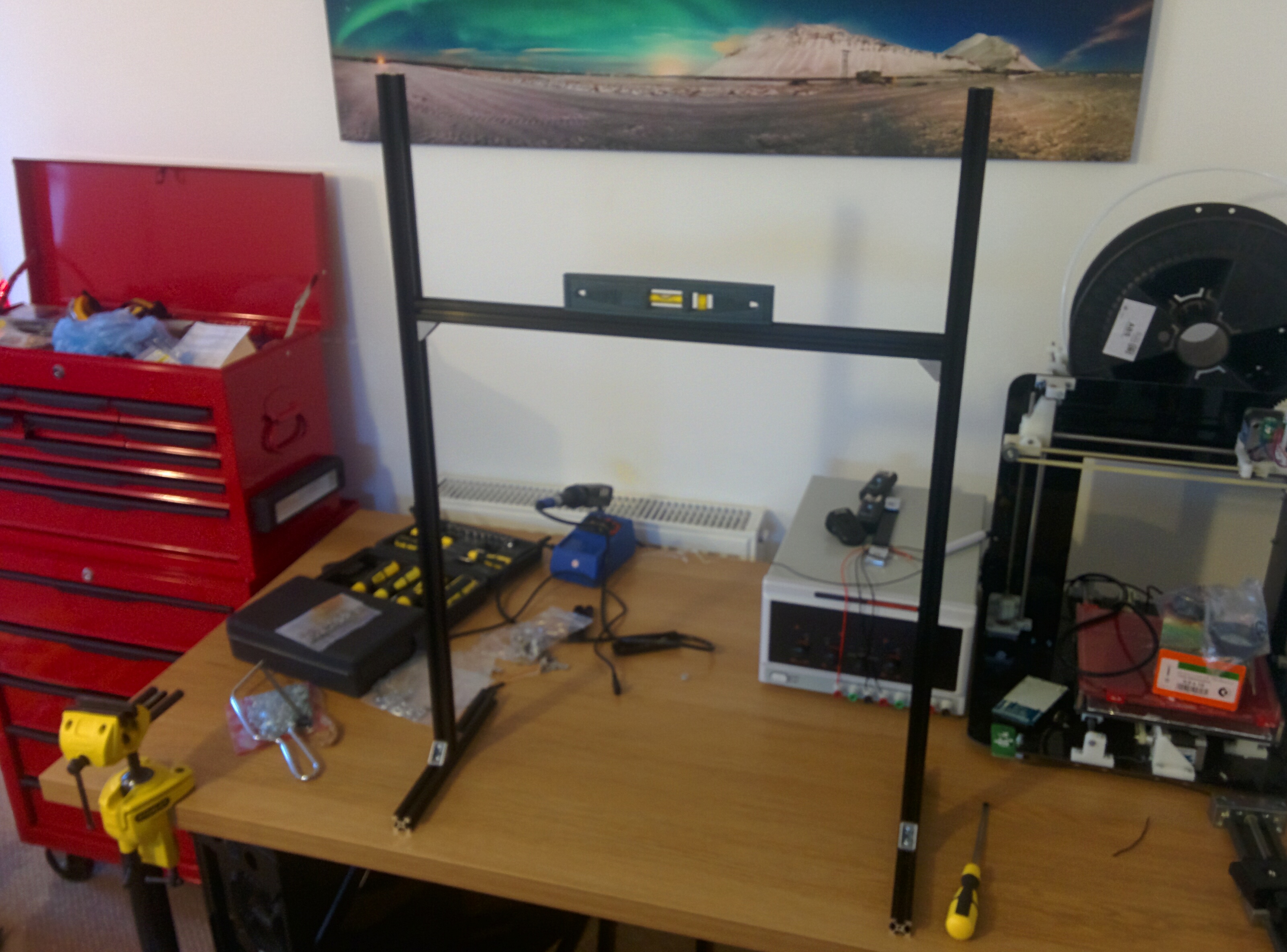
Extruded aluminium frame
Dimensions of the frame are: 250mm for the feet, 750mm for the uprights, and 500mm for the horizontal. I figured this would provide a good height for producing the drops, leave plenty of room for the container being dropped in to and the exposed upright sections above the horizontal, where the valves are mounted, will be ideal for attaching the reservoirs with some cable ties.
Start of the electronics…
I’ve only done some of the basic electronics at this stage. Primarily wiring up the 2V025-08 solenoid valves and working on trigger cables for the flashes and camera. An interesting interaction I noticed, I shoot with a Sony A99 but also have my old A700, by re-purposing the proprietary connector from a cheap ebay trigger for my camera I was able to get the A99 firing in manual mode off of just the shutter trigger, the A700 on the other hand requires both the focus and shutter to be triggered for the camera to fire even in manual focus mode. Trigger operation is simply a case of closing the circuit across the pins of the connector, similarly for the flash guns.
A little researching online recommended the use of optoisolators to do this as it ensures that the control circuitry remains completely isolated from the camera circuitry ensuring no risk of stray currents or voltages to the camera. I’m using 4n26 isolators and the wiring of these is incredibly simple. Just got photos of the process for now, will have schematic pictures ready for part 2.
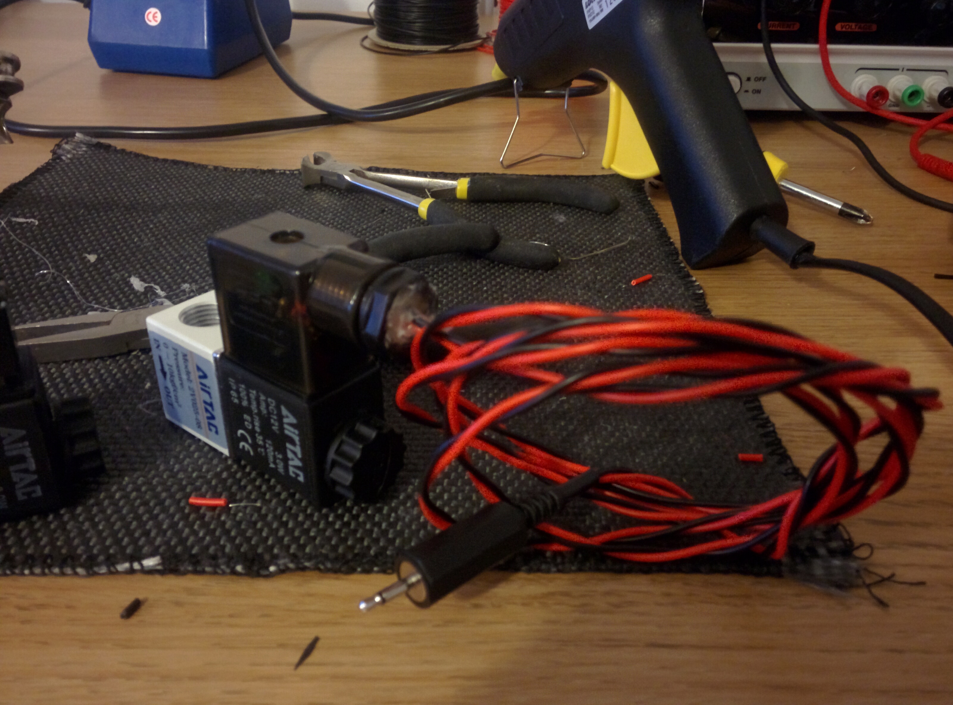
Solenoid valve wiring
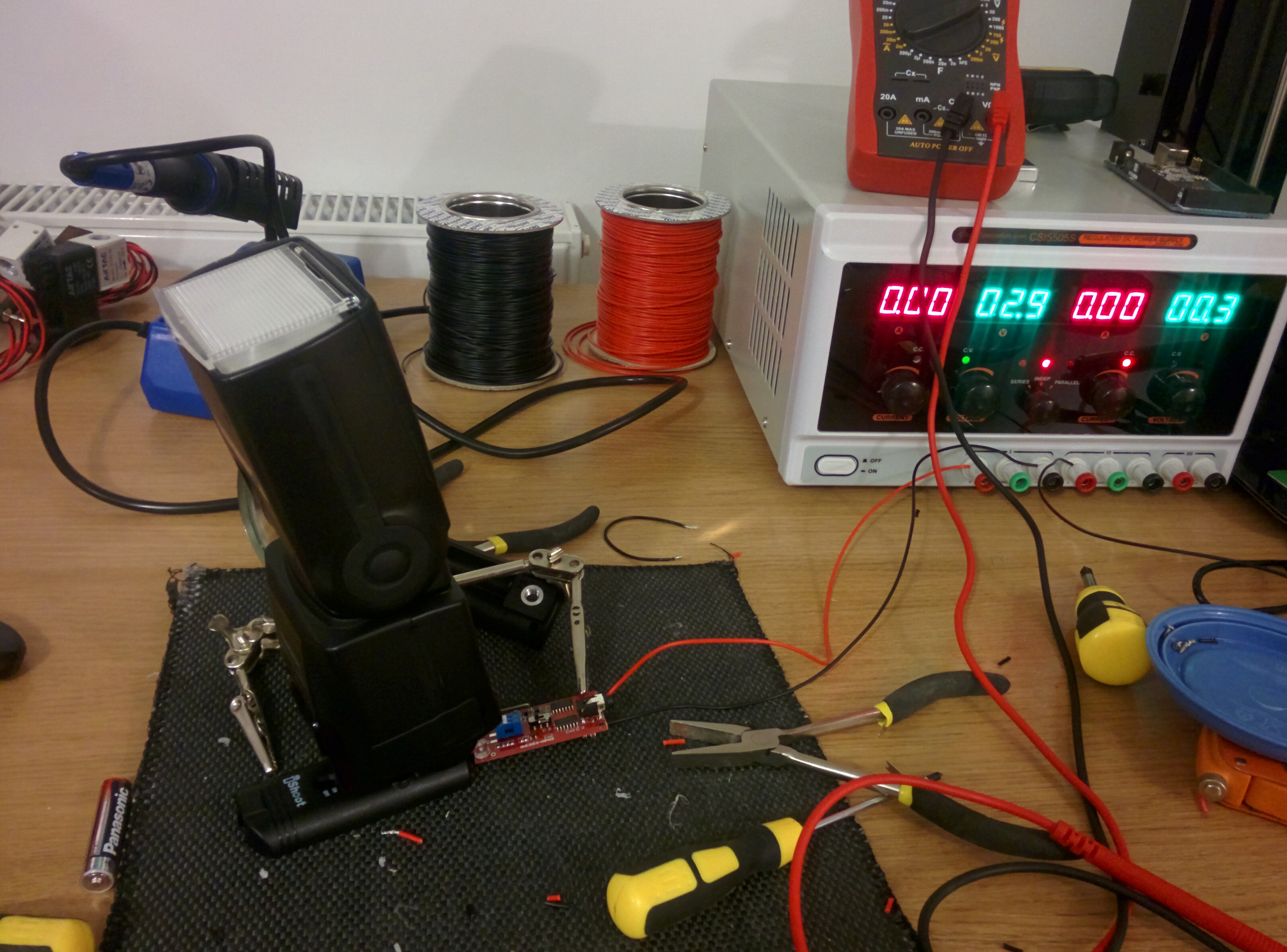
Triggering flash through the socket
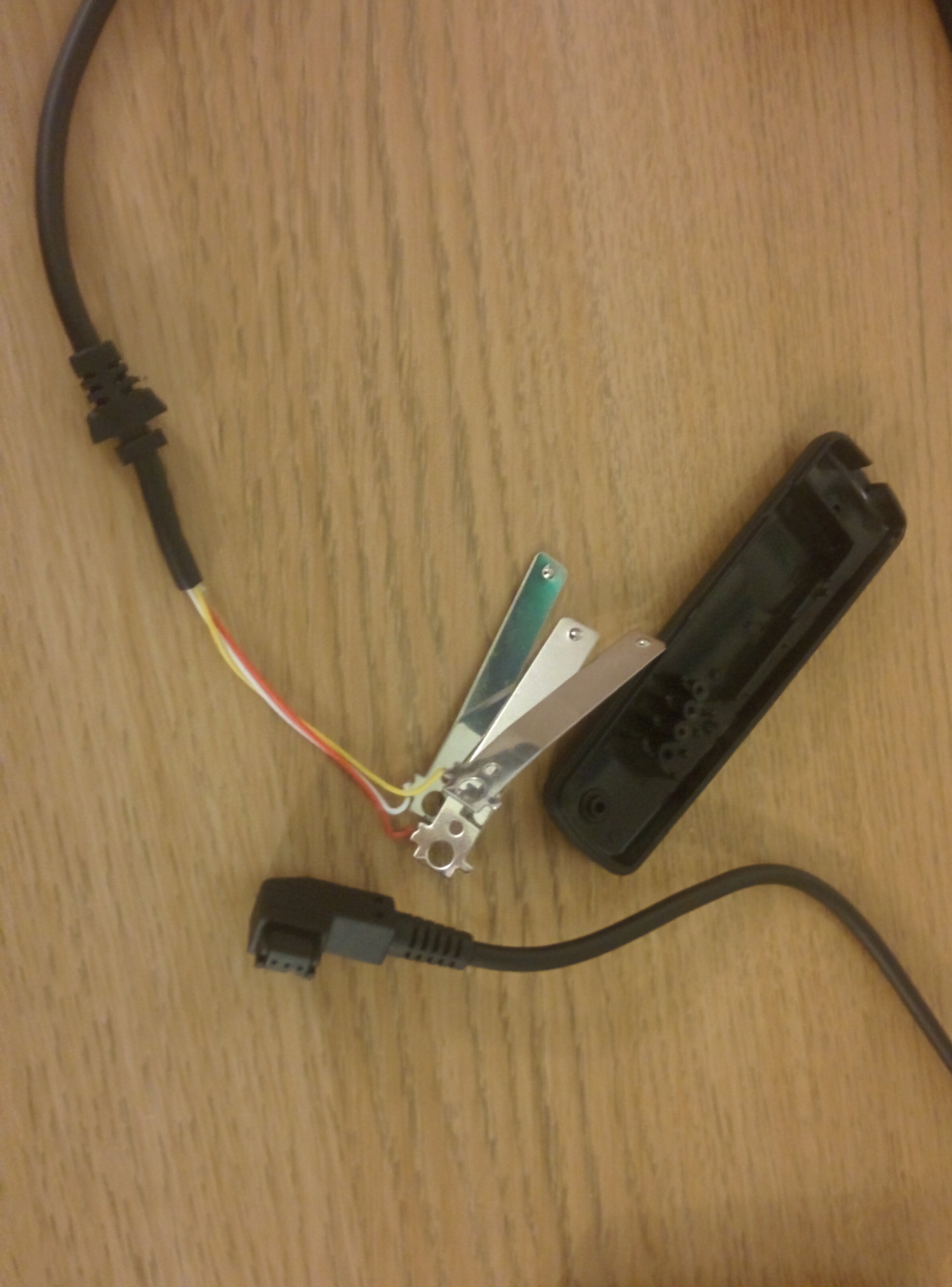
Dismantling trigger for the sony plug end
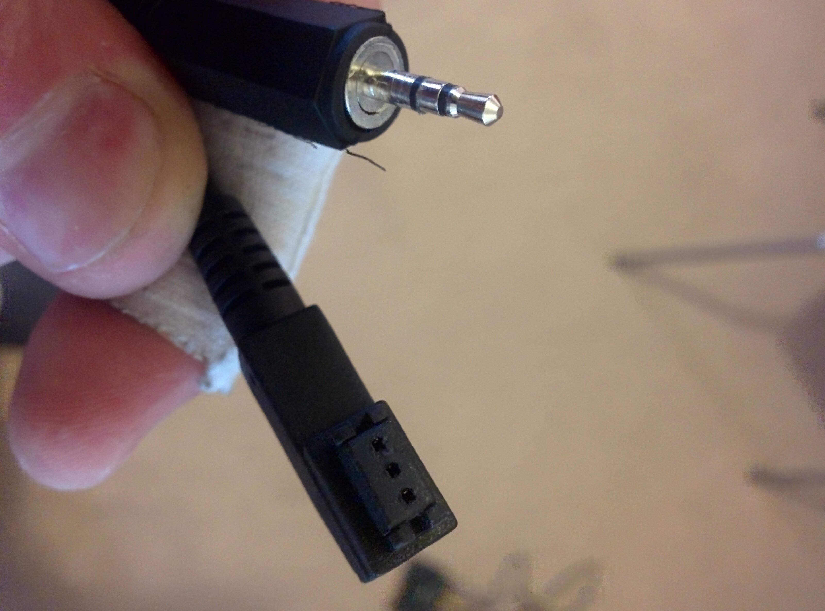
New camera trigger cable wired up to 2.5mm stereo plug
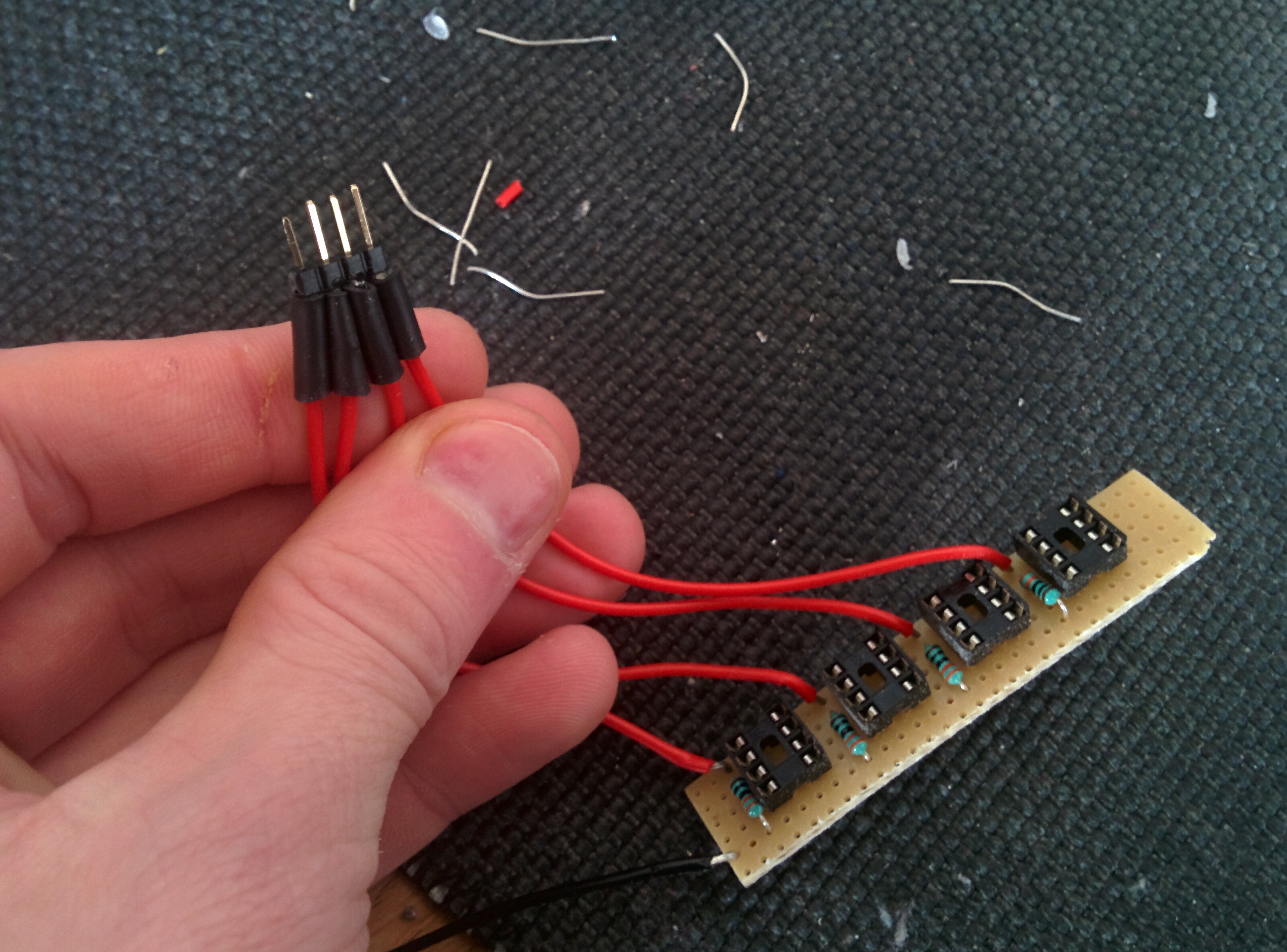
Wiring up opto-isolators for camera shutter, camera focus and two flash guns. Not quite finished yet.
Coming up…
Hopefully in part 2 I’ll have more of the electronics finished and some of the programming done. If you have any questions regarding what I’m doing please don’t hesitate to get in touch, would love to hear from you if you’re doing something similar.