Builds : Waterdrop Rig Part 2
In the two weeks since my last project udpate I have been working pretty hard in my evenings and weekends soldering away to get this project completed, not as easy as it sounds when I spend most my time at work soldering and designing circuits only to come home and do exactly the same thing; it’s a good job I enjoy it.I ended up breaking down the controller in to its individual elements and constructed each of these boards seperately. This meant that alongside the brains of the controller, an Arduino Uno, there were the following separate modules and boards:
- Power Rail
- Valve control
- Front panel
- IR Trigger
- Trigger Controllers
As a complete unit, the electrical design is pretty simple, probably a few things that could be specified better to improve speeds but the majority of the control complexity will come from the actual software.
Power Rail Board
Utilising a single power rail board is something I’ve opted for in a lot of my recent projects. I find that rather than attempting to jump wires all over the place, the electronics remains much more manageable and easier to debug if I simply provide a single rail in which all additional boards receive power from. For the purpose of this build, the entire system is being powered by a 12v adaptor, the solenoid valves I have selected (very generic ones off of ebay) run off of 12v, and everything else runs at 5v provided by the voltage regulator on board the Arduino which will provide enough juice for this project.
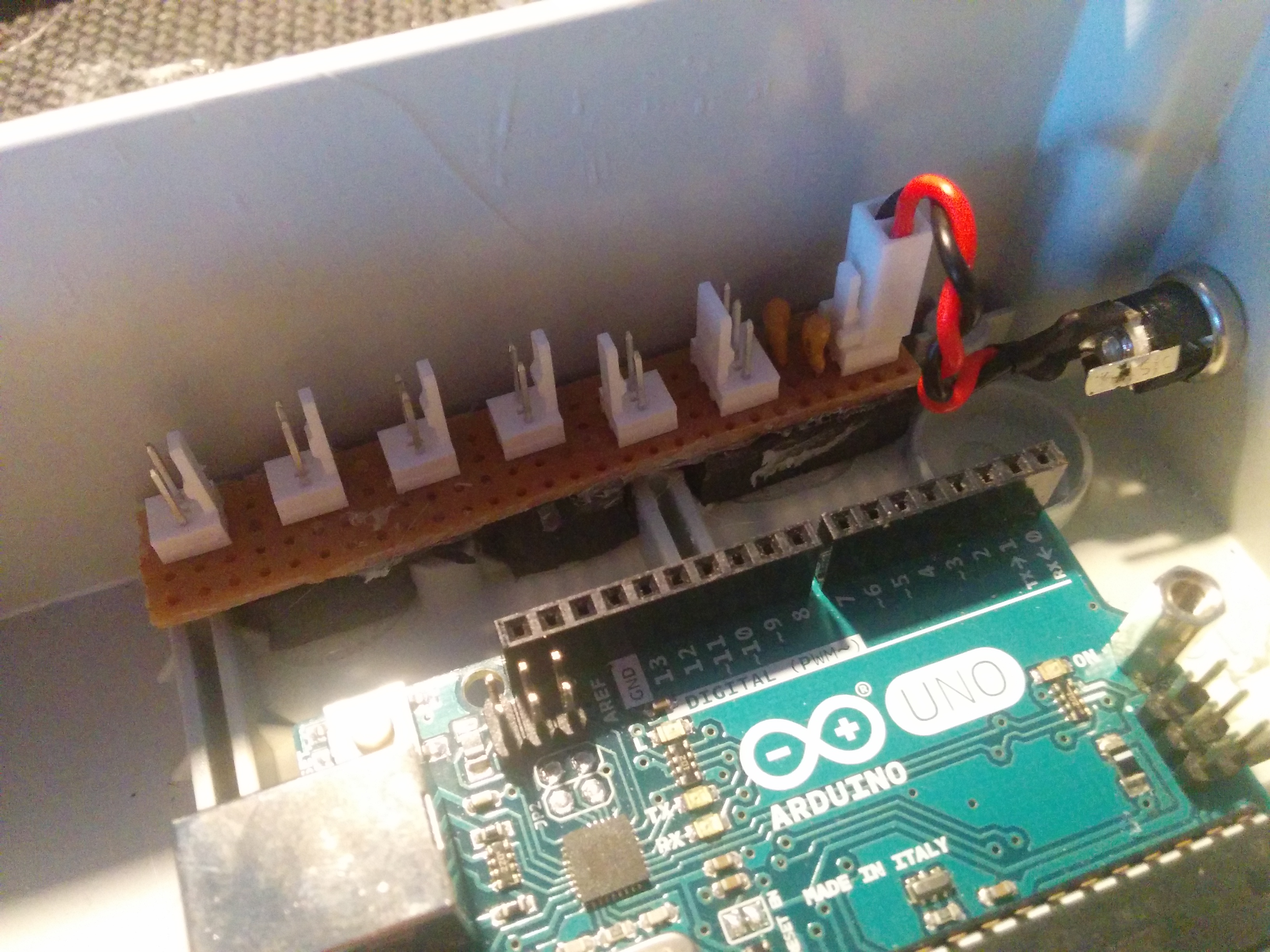
For the final build of the controller, which came about after many rewiring attempts due to my inability to size wire lengths correctly I have utilised molex kk series connectors for ease of connection and disconnection of various modules from the system for testing and installation.
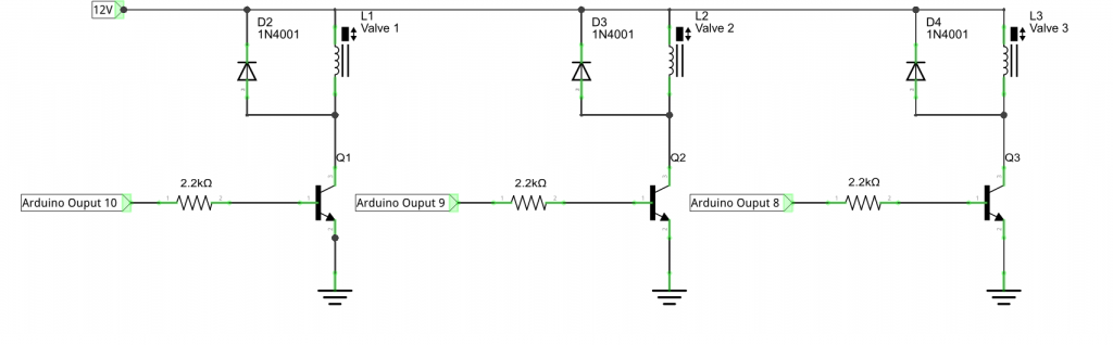
Valve Control Board
Valve control takes advantage of the low current draw of the solenoids of approximate 100mA and just switches power on and off through an NPN transistor. I have included flyback diodes across the solenoids to counteract back EMF and valve connection is done through 2.mm mono jack socket.
Front Panel
The front panel consists of the user inputs and screen. I’ve chosen to use a 4×20 monochrome LCD for the screen and this should give me enough space to display all the informaion I need to. These screens are also really easy to interact with making use of only 6 of the Arduinos outputs. I’ve also made a very small board for the screen to cut down on power connections to just two wires (5V and GND).
Alongside the screen are 5 PTM switches that will be configured to act as a directional pad and a selection switch. In hindsight I would have liked some lighter touch and smaller buttons as these required a pretty heavy touch to operate.
IR Trigger
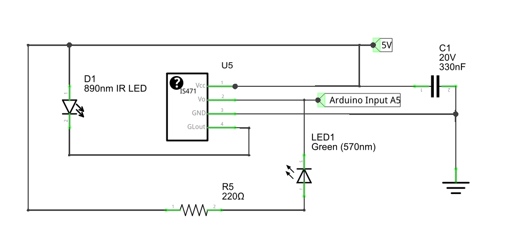
The IR trigger I have made is probably a little overkill and may require some rework. I’m currently using an IS471 IR detector which includes a built in modulator to control the IR LED to eliminate the effect of outside IR interference, like I say, overkill, but may prove beneficial. This is connected to the main controller through a 2.5mm stereo jack plug. I also included a visible LED on the board that lights when the detector can see the IR LED which should help in setting up.
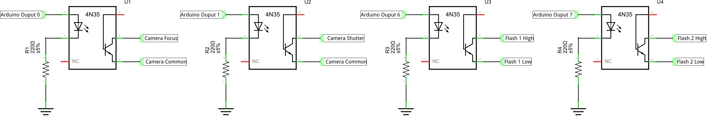
Trigger Controller Board
To remove the potential for any stray currents or voltages reaching the camera electronics I am using 4N26 optoisolator ICs. These little chips consist of a built in diode and photodetector that connects the outputs when the diode is powered whilst also ensuring the two circuits are electrically isolated. They are incredibly simple to wire as shown in the schematic. Four of these ICs allows me to individually control the camera shutter and focus (connected through a 2.5mm stereo jack) and two flash guns (connected through 2.5mm mono stereo jacks).
The completed electronics ends up using all but one of the Arduino Uno’s IO pins.

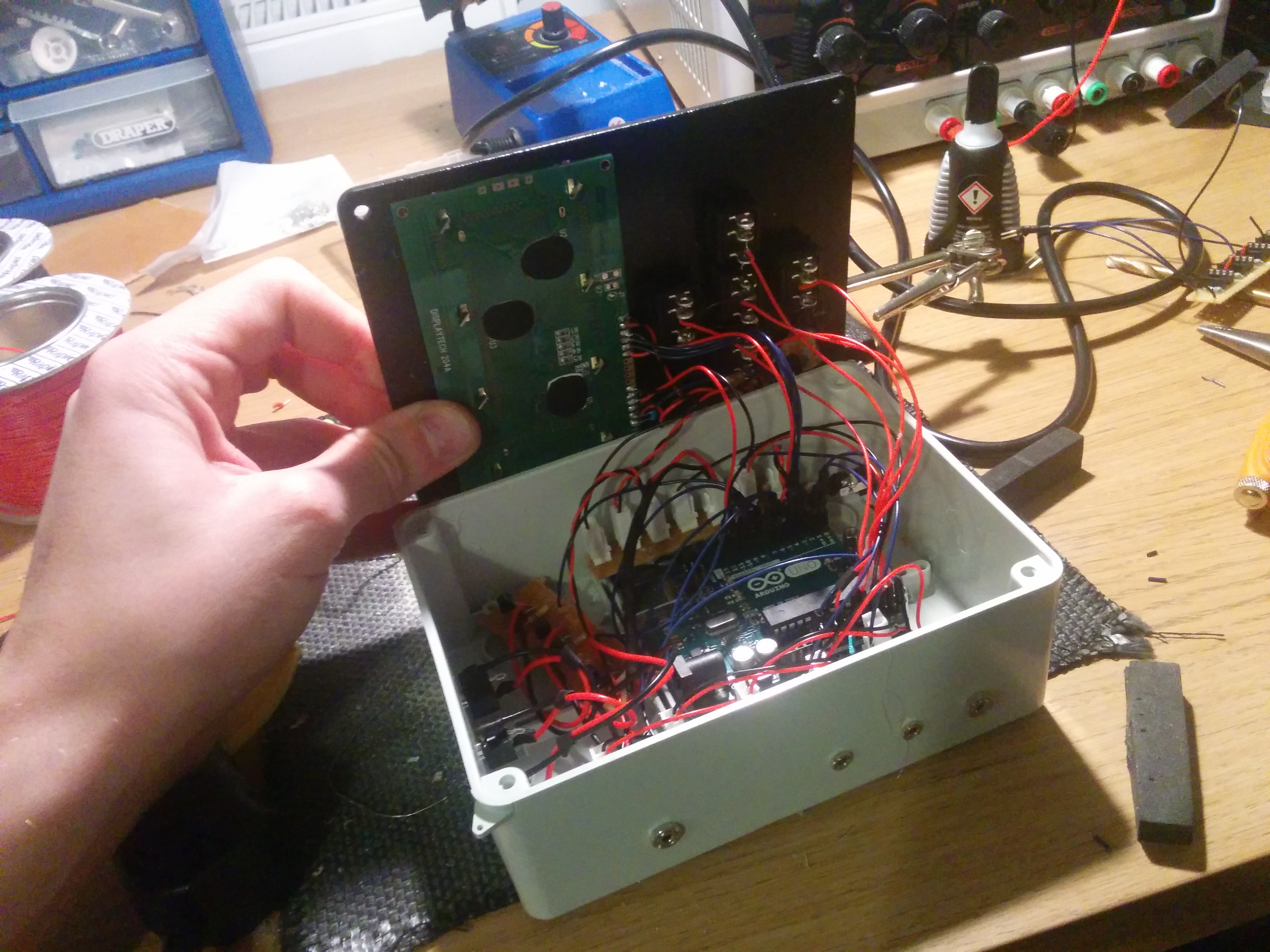
Inside the controller
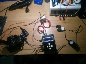
Completed system with valves and triggers connected
Software Design and User Interaction
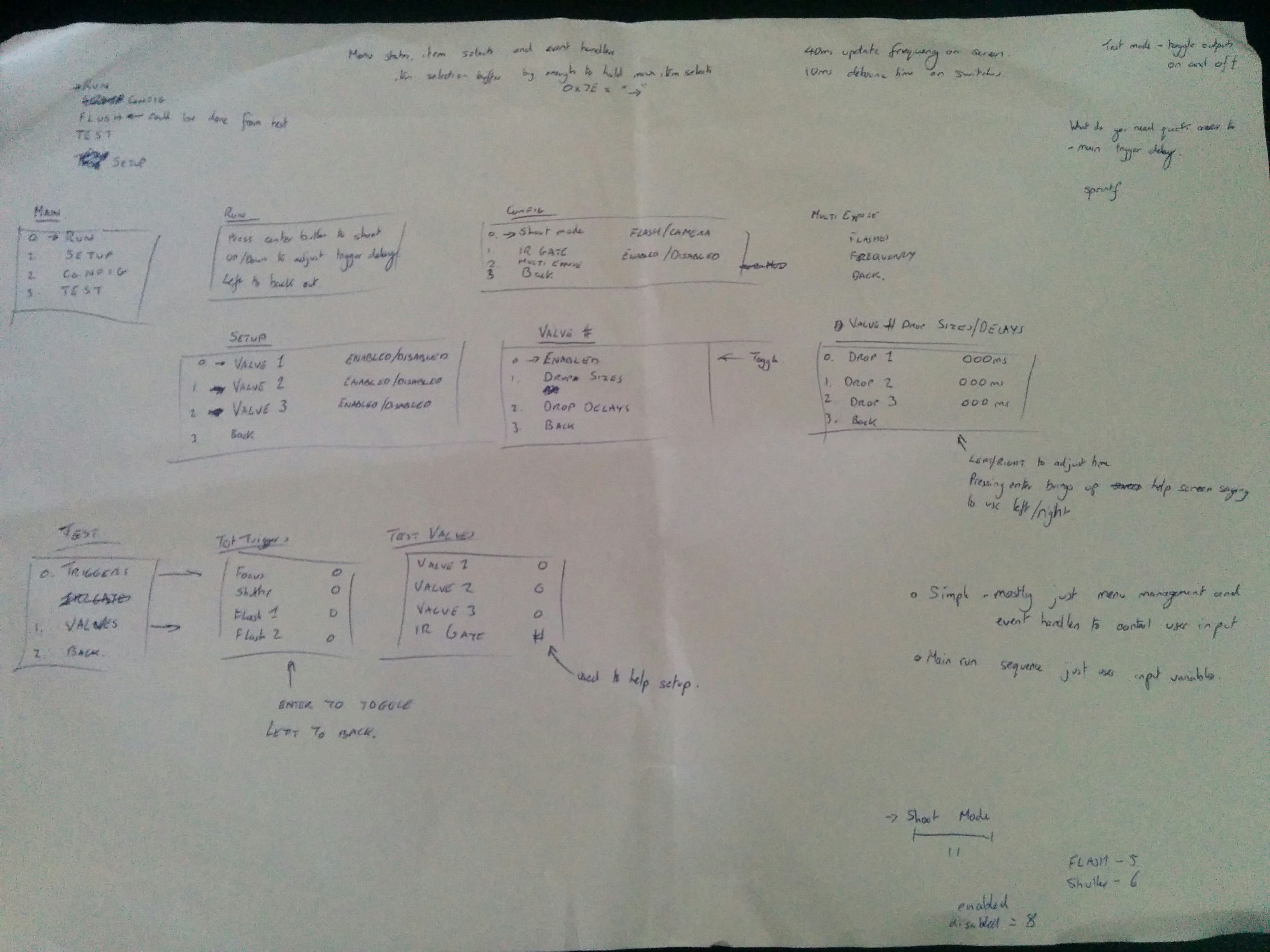
State machine architecture based off of menus
Now that the hardware was all completed and tested, next came the controller software. Being unsure exactly what I would require out of the controller I decided that too much control would be better than too little as so outlined the software architecture as a state machine consisting of different user menus each allowing control over different elements.
I had to be very careful with the user interaction during each state ensuring that it was as expected and consistent but then did not overly complicate the interaction and increase the depth of sub menus and controls unnecssarily.
The final software was complete in a single afternoon and evening of coding so could probably do with a bit of a rework and tidy up down the line but I’m pretty happy with the level of interaction and control available.
The final software consists of:
Run Menu: This is used to initiate a drop sequence after setting the other parameters. There is quick control access to the flash trigger delay on this screen to elimate unecessary menu depth and breadth.
Test Menu: This allows toggling of the output triggers and valves. Pretty useful to just test the system isn’t malfunctioning and I’m hoping the valve control can be used as a good way of “flushing” out the system at the end of use.
Config menu: In here it is possible to set the trigger mode and whether the IR gate should be used or not.
Setup Menu: From here it is possible to toggle each of the three valves as enabled or not and then set up, up to three drops per valve which includes their drop delay time and their size (size determined by valve on time in ms).
Coming up…
Coming up part 3, I should have a video showing the controller operation and hopefully, the first photos.